With the number of network connections needed to support 10 Gigabit Ethernet (10GbE) growing in data centers, a modern solution is needed to keep patching fields from becoming too congested. Introducing ultra-high-density cabling to data centers is a vast improvement over traditional fiber cabling. Using MPO and MTP connectors and cables will help integrate fiber into a single interface and support the next technologies of 40 GbE and 100 GbE.
Multi Fiber Push On (MPO)
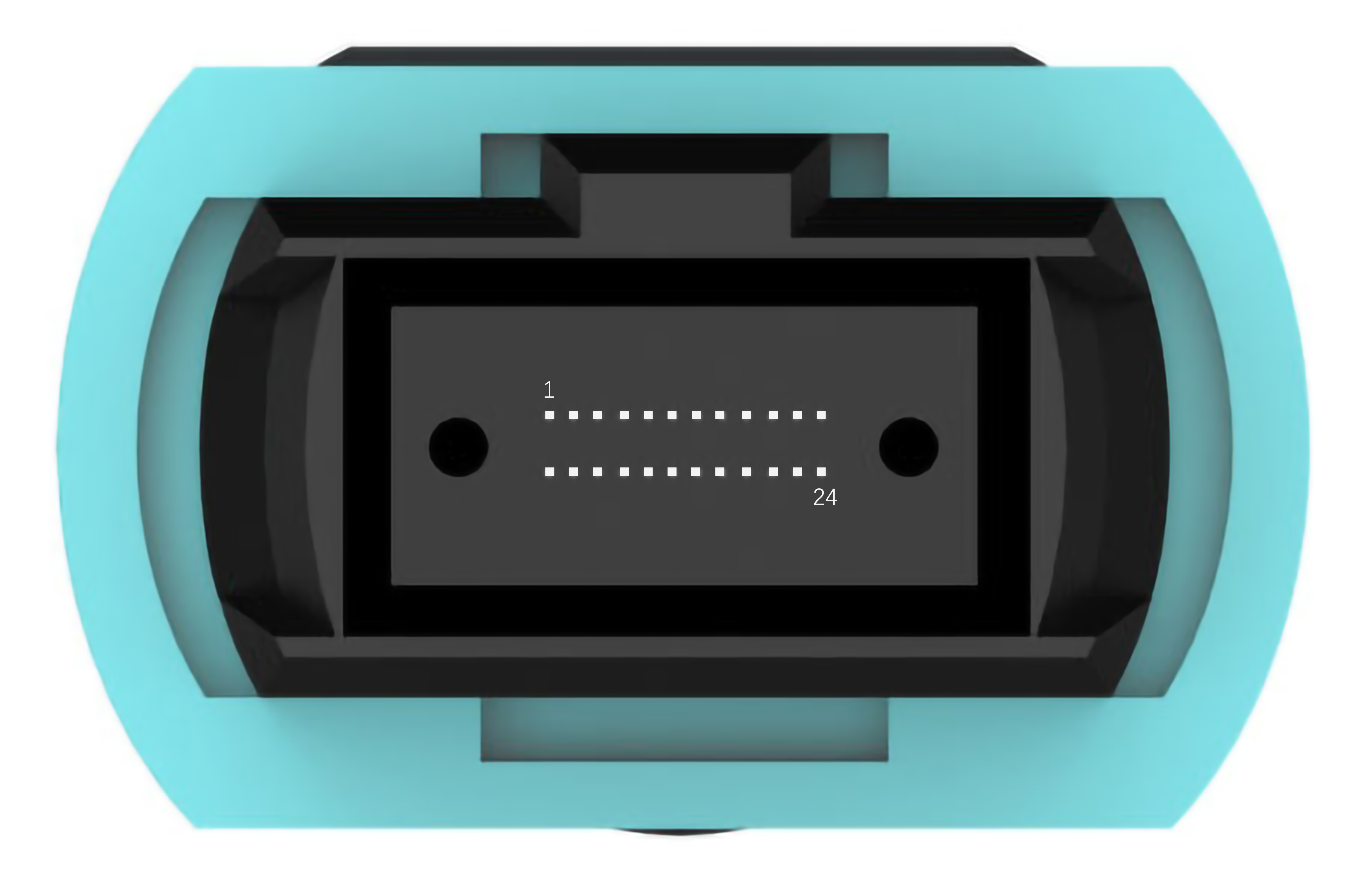
Multi Fiber Push On, also known as MPO, was originally manufactured to facilitate high-density termination and support high speed communication networks. What started as a 12-fiber single row connector, has now evolved into 8 and 16 single row fibers that have the capability to be stacked together to create 24, 36 and 72 fiber connectors while using multiple precision ferrules. The standard for these MPO styles has been established by the International Electrotechnical Commission (IEC) and the Telecommunications Industry Association (TIA). The international standard is known as IEC-61754-7 where as the TIA standard is TIA-604-5.
MT Ferrule
The mechanical transfer ferrule, a multi-fiber ferrule, is important for fiber alignment. It’s required to hold intense tolerances for precision during the molding process as this affects the shape, tolerance and material composition of alignment pins. The result will determine the alignment of the pins and holes as well as the eccentricity and pitch of the fiber.
MTP Connector
MTP connectors are designed to enhance optical signal and mechanical performance while providing lower insertion loss over MPO connectors. The ferrule of the MTP connector floats to retain physical contact on mated pairs if there is strain on the cable. The elliptical shaped, stainless steel guided pins in an MTP connector are less likely to cause damage compared to an MPO connector’s pins. The MPO connector has chamfered guided pins that can chip the ferrule and cause the material to drop into the guided pin holes or on the ferrule end face. MTP connectors are built with metal pin clamps that help center the push spring. The spring design prevents damage by maximizing ribbon clearance for 12 fiber and multifiber applications. A variety of MTP connectors are offered to accommodate a variety of applications: Type of boot, round or loose fiber cable, oval jacket or bare ribbon fiber, just to name a few.

Compatibility
MPO connectors can directly interconnect with other MPO based infrastructures, due to being compliant with MTP standards outlines in IEC standard 61754-7 and TI-604-5.
Wiring
Below are the four types of wiring using 12-pin MTP connector: Straight-through, cross-over, pair flipped, and universal.
Straight through, pair flipped and Universal wiring are all configured key up to key-down for mirrored signals. However, they do vary based on their uses. Straight through wiring are mostly used for patch panels. Pair flipped wiring incorporates a duplex pair-wise flip with the fiber location left to right connector and universal wiring incorporates an even/odd flip with the same left to right fiber location. Cross-over wiring is configured as key-up to key-up with unmirrored signals. Crossover uses include switches, transceivers, and electronic devices.
| Type | Internal Connection | Connector |
|---|
| Type A (Straight-through) | 1:1 | Key up to Key down |
| Type B (Cross-over) | Crossed | Key up to Key up |
| Type C (Pair Flipped) | Pairs Crossed | Key up to Key down |
| Universal |
| Key up to Key down |
Type A (Straight-through)

| Connector | Fiber Arrangement (with Key up view) |
|---|
| A | 1 | 2 | 3 | 4 | 5 | 6 | 7 | 8 | 9 | 10 | 11 | 12 |
| B | 1 | 2 | 3 | 4 | 5 | 6 | 7 | 8 | 9 | 10 | 11 | 12 |


Type B (Cross-over)

| Connector | Fiber Arrangement (with Key up view) |
|---|
| A | 1 | 2 | 3 | 4 | 5 | 6 | 7 | 8 | 9 | 10 | 11 | 12 |
| B | 12 | 11 | 10 | 9 | 8 | 7 | 6 | 5 | 4 | 3 | 2 | 1
|
Type C (Pair Flipped)

| Connector | Fiber Arrangement (with Key up view) |
|---|
| A | 1 | 2 | 3 | 4 | 5 | 6 | 7 | 8 | 9 | 10 | 11 | 12 |
| B | 2 | 1 | 4 | 3 | 6 | 5 | 8 | 7 | 10 | 9 | 12 | 11
|
Universal

| Connector | Fiber Arrangement (with Key up view) |
|---|
| A | 1 | 2 | 3 | 4 | 5 | 6 | 7 | 8 | 9 | 10 | 11 | 12 |
| B | 1 | 3 | 5 | 7 | 9 | 11 | 12 | 10 | 8 | 6 | 4 | 2 |
Performance
MTP connectors work best when used with other MTP connectors and offer a superior lifetime performance when compared to MPO.
MTP is a registered trademark of US Conec Ltd.®